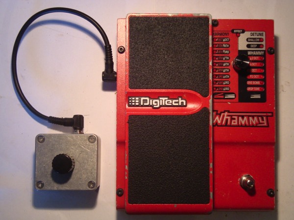
Making a Whammy IV Remote Switchable - via an External Encoder Box
I like to play my Rhodes through a Whammy in certain settings, and sometimes, I like to switch it's effect programs as I'm playing. Up to now, I've had to reach to the floor underneath the keyboard and operate the Whammy's rotary encoder everytime I wanted a program change - which is somewhat annoying, plus, it looks kind of weird on stage during a performance. So I came up with this idea to have the Whammy's rotary encoder doubled in an external little box which I can place anywhere I wish.

a) it's not as fast as dialing by hand
b) when I want to switch between two not exactly neighbouring programs, chances are people in the audience are going to hear me go "click click click" as I keep stomping that box
c) using the encoder while holding a sustained note creates a nice effect as I quickly circle through the different harmonizations - which just isn't possible with a pedal switch.
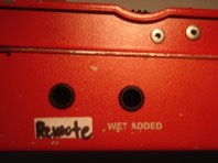
Next to the "Wet Out", there's another TRS output that carries the dry, unprocessed signal. Since I never used it, I modified it so as to be directly connected to the internal rotary encoder which actually switches between the programs. Now all I had to do was get an encoder of the same type, put it in an external little box and connect that to the Whammy - so I have my external encoder effectively in parallel with the internal one but can place the external box wherever I please.
Following is a detailed description of everything I did - and that without even having a schematic!
above: Whammy with some screws already removed
left: Modified "Dry Out"
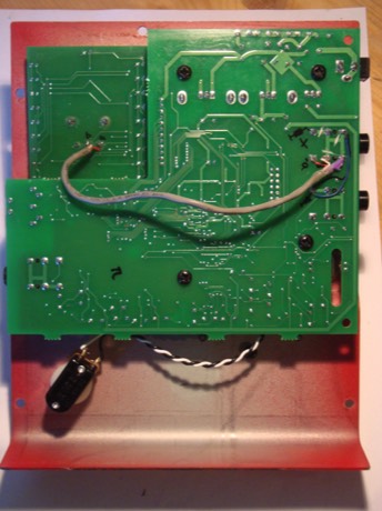
below: back of faceplate with the PCB turned over
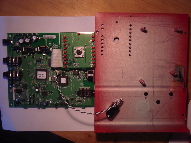
First, I loosened all screws on the top and at the MIDI connector, then shifted the upper part of the housing slightly to the left, whereupon it comes apart nicely. After loosening all screws of the printed circuit boards (PCB) and turning those over, I got the picture as shown below.
On the main PCB's left edge, there are the connectors for power, Dry Out and Wet Out (top to bottom). At the top right, there's the little daughter board with the encoder and LED's for making and displaying a program change.
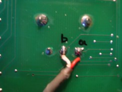
Examining the encoder, I found that it has three terminals (labelled a, b and 0 on the picture). There are two more contacts soldered to the PCB, which, however, have no electronic function but are just for mechanical stability.
As the encoder is turned, two out of its three terminals make contact temporarily for each step, a - 0 for one direction, b - 0 for the other. By checking for continuity (e.g. using the Resistance or the "Diode" setting in a Digital Volt Meter), I found out which terminal is which and labelled it accordingly. To double this externally, I would have to hook up the external encoder in parallel with the internal one, connecting the terminals of the former with the respective terminals of the latter.
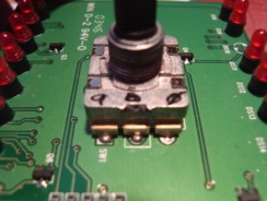
By checking for continuity between Ground on the PCB and any of the three terminals, I found that the "0" terminal is actually connected to Ground.
(How do I know where to find Ground in an unknown circuit? Well, e.g. by using the "Sleeve" terminal of a TS or TRS connector, which is always connected to ground on the PCB; since the Sleeve contact of a 1/4" jack connector is attached to the cable shield, it has to be at ground potential in order to actually shield the core wire(s) from external noise)
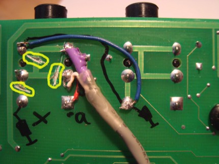
I used a piece of shielded balanced cable and soldered it's two core wires to the solder points of terminals a and b on the back side of the PCB - shrink-tubing the end so the shield would not touch any other soldering points.
(picture to the right)
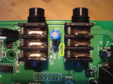
The TRS connectors on the PCB are of the switching type; they have six contacts altogether, three on each side of the housing (see picture showing back of PCB).
When no jack is inserted, the three metal tongues attached to one side make contact with the respective pins on the other side.
Upon insertion of a jack connector, the three tongues are lifted from these pins and make contact with the Tip, Ring and Sleeve areas (TRS) of the Jack instead.
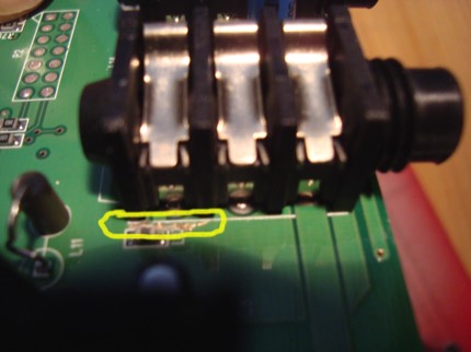
In order to isolate the "Dry Out" connector from the rest of the circuit, I had to cut all PCB traces connected to the Tip and Ring contact, since I was going to use those for the A and B terminals of the encoder.
As indicated by the yellow markings, I cut the respective traces near the connector on the component side, as well as some traces on the solder side. I used a small screwdriver for cutting the traces open, plus a soldering iron and compressed air for cleaning up any remaining particles from the board.
After that, I soldered both wires of the cable to the T / R contacts, plus the shield to the S contact, which is connected to PCB ground. I didn't solder the other end of the shield to the "0" pin of the encoder, since it's connected to PCB ground, too. Otherwise, I might even have created a ground loop which may have caused noise problems.
(The blue wire is just there to ensure that the row of switching contacts for the audio input is actually at ground potential, since I wasn't sure if I maybe one of the cut traces on the other side would have prevented this)
Pictured to the right is the PCB mounted back onto the faceplate, with the finished internal mod. Now, all three terminals of the internal encoder are linked to the former "Dry Out" Jack connector.
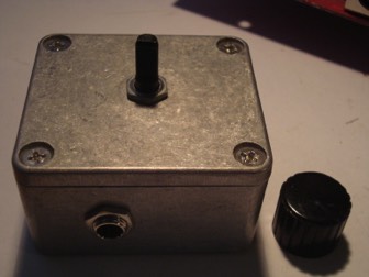
For the external box, I needed a rugged housing, a TRS 1/4" connector, the, well, encoder itself plus a knob to fit it's shaft. The housing I found at my local electronics store was a die-cast aluminium box, sized ca. 5 x 5 x 3 cm.
There, I also found this encoder with 24 steps for 360° rotation, which gives a feel similar to the original one. I had to make sure that I'm getting a model with a threaded axis because there would be no PCB in my little box to solder it to, so all mechanical support would have to come from the axis mounted to the top of the box.
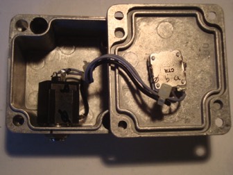
By use of a drill press, I punched holes for the encoder and the TRS connector and mounted them as pictured.
Using three short pieces of wire, I hooked up the terminals of the encoder to the connector; a - Tip, b - Ring and 0 - Sleeve, matching the pin-out at the Whammy.
Now I can connect this box to the Whammy via a regular balanced TRS cable and place it anywhere.
Done!