LESLIE 147
Overview Of The Amplifier
As an estimate, my Leslie was built somewhere in the 1970ies and thus is around 40 years old (for tips on Leslie and Hammond age determination, go here). Within four decades of use, electrolytic caps may dry out and loose capacitance, resistors may drift in value, so may the parameters of tubes - a check of the amplifier definitely was in order. After loosening just one screw, the amp can be pulled out of the cabinet.
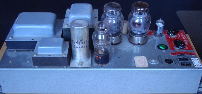
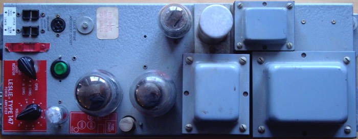
The picture below shows a top view of the amp. To the left, there's the input resistance switch and volume control, plus connectors for the upper motors as well as the round 5-pin plug for an optional brake arrangement. In the bottom row, we have the 12AU7 tube for the preamp stage, the two 6550 power tubes, their associated wirewound cathode resistor (the small white cylinder, which actually gets so hot by the idle current that it needs to stick out from the chassis), the output transformer (middle) and power transformer (left). At the top, there are OC-3 stabilizer tube, multi-capacitor can and inductor choke from the power supply section. The greenish thing above the 12AU7 tube is a power switch for the amp, which has been added by someone.
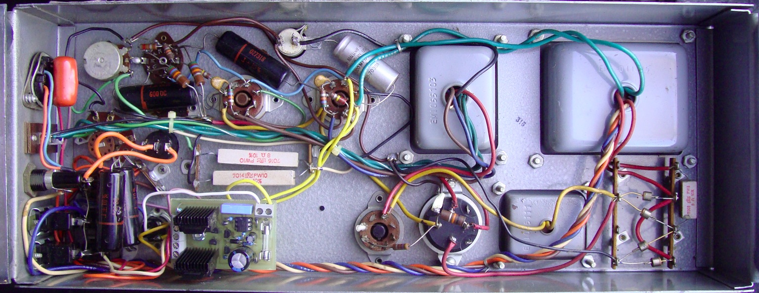
With the amplifier turned over, we get to see the innards. As it was custom with tube equipment of those days, the components are hand wired, with the resistors, diodes and smaller capacitors mostly centered around sockets, switches etc., or on posts. The bridge rectifier of the PSU is to the far left, the two grey longish things more to the right are the input resistors for 8 / 16 Ohms termination. Some of the areas look rather crammed, but when tracking the individual leads and colors schemes closely, it's something you can deal with. Note that the PSU section is star grounded to the chassis at the bottom left screw of the output transformer, while filament and audio ground meet at the top of the 10K input pot, from where they are referenced back to the star grounding point - obviously the optimum grounding scheme for minimal hum.
By the way, the mylar capacitors used here can have various colours and shapes, depending on the brand used in the respective year of production. Lastly, in place of the original relay, there's a small printed circuit board employing solid state switching, made by Michael Ansorge. It's powered off the filament supply (yellow leads to 6550 socket).
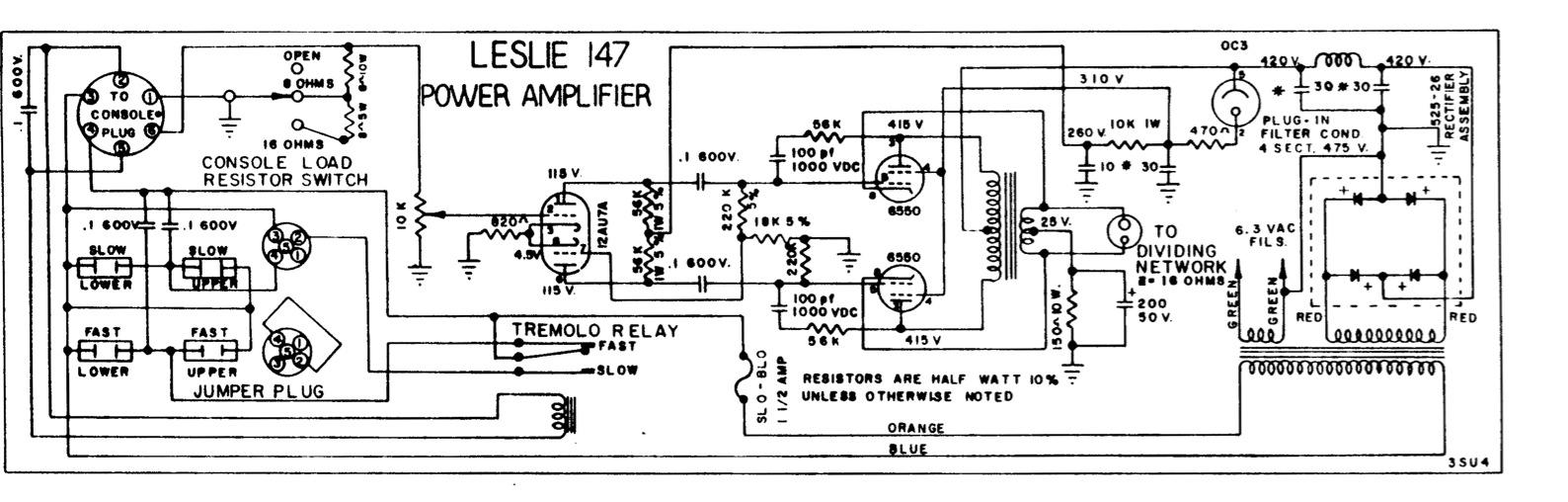
Looking at the physical layout of the circuit, we can see that it's somewhat similar to the order in schematic above. The male 6-pin connector is pictured on the upper left corner. Pins 3 & 4 carry AC power, which is fed to the connectors for fast or slow motors depending on the position of the Tremolo Relay. Its position, in turn, depends on wether there's AC power across the relay coil (or, in my case, across the terminals of the solid state relay unit) which is applied to pins 2 & 5 by an external switch. The AC from pins 3 & 4 also goes to the power transformer on the very right, the secondaries of which carry filament (green) and anode supply (red).
After the diode rectifier, the anode supply passes through a "pi" filter consisting of an inductor and two capacitors, which feeds the two plates of the 6550 power tubes through the output transformer's primary center tap. Another branch goes through the OC3 stabilizer tube and two RC filter stages. The control grid voltage for the 6550's is taken off the first stage, the second stage feeds the anodes of the 12AU7 (ECC82) double triode in the preamp stage.
Checking Values And Voltages
In the PSU filter, the four electrolytic capacitors (residing in the plug-in can mentioned above) met or exceeded the required values; their leakage resistance was 5 MegOhms or more, which is also fine. The rest of the capacitors, as well as the resistors, measured similarly well. Only the two 56K anode resistors of the preamp stage had drifted noticeably upwards in value, where one was more off (+10%) than the other (+5%). In terms of fidelity, that would be critical, since in this type of circuit, the balancing of the signal coming from the preamp should in principal be as good as possible - but as we're actually looking for some distortion at higher signal levels with this type of Leslie, I left it alone.
Switching on the power, I was able to measure all supply voltages given in the schematic within -5 to -10% tolerance, which seemed OK for the time being. To check the distortion characteristics by applying a sine signal, I connected some power resistors with an equivalent value of 16 Ohms, which would load the amp appropriately. For an input of 2,3Vpp, I got around 20Vpp at the output, with visual distortion setting in at around 25Vpp. The output was slightly non-symmetrical, probably due to the imperfect balancing of the preamp stage, resulting in different amplitudes fed to the power tubes and thus slightly different half waves at the output. Also, there was some crossover distortion appearing at higher levels - again, I considered this to be part of the "vintage crunch" of Leslie sound and left it alone at first. To what extent this effect (as well as the audible "sagging" of volume at high levels as I pulled out more drawbars) can be attributed to component imperfections, such as increased ESR in the PSU capacitors, will be addressed in the last chapter.
With the amp operating fairly well for it's age, now it was for the horn driver issue to get fixed...