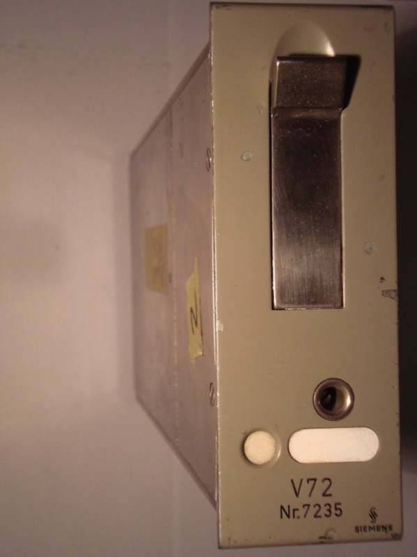
DISSECTING A V72
While servicing one of my units, I thought - while you're at it, why not take it apart all the way. So, here goes...
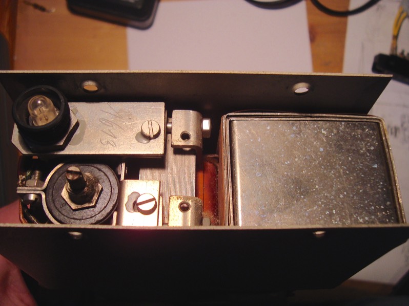
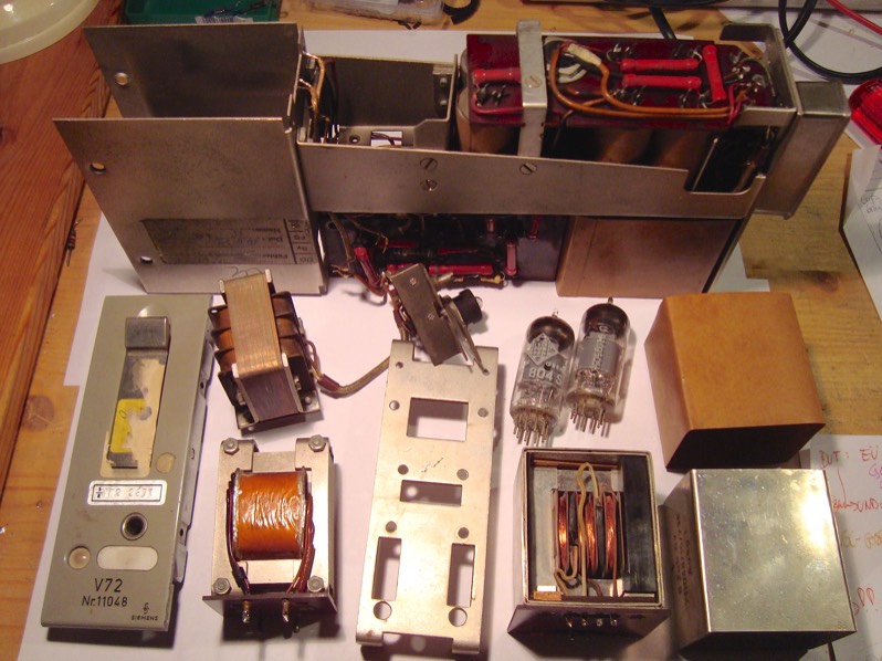
Transformer section
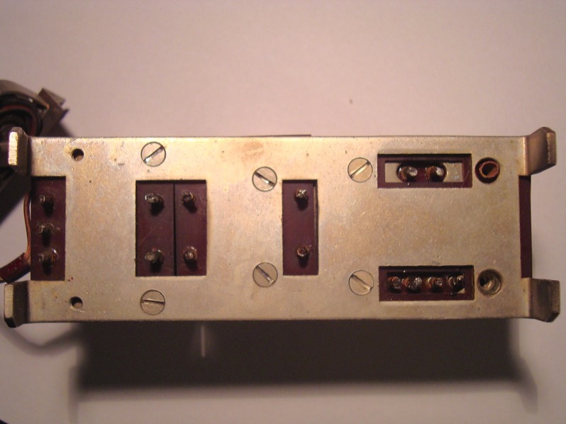
The complete section sits on a cross sheet which can be detached from the chassis by loosening four screws. Before that, I must also desolder all wires connecting to the rest of the circuit (some of which are a pain to get to), including those leading to the "de-hummer" pot at the faceplate, which balances the filament supply with respect to 0V potential. In order to pull out the transformer section towards the front, the pot plus the whole faceplate need to be taken off as well.
By the way, when soldering transformers or inductors on these old units, you want to be especially careful not to stay too long with the iron, since there's a chance that the insulation of the internal windings - or, in case of a very small diameter, even the internal wire itself - might fail because of the heat.
While servicing one of my units, I thought - while you're at it, why not take it apart all the way. So, here goes...
Transformer section
The complete section sits on a cross sheet which can be detached from the chassis by loosening four screws. Before that, I must also desolder all wires connecting to the rest of the circuit (some of which are a pain to get to), including those leading to the "de-hummer" pot at the faceplate, which balances the filament supply with respect to 0V potential. In order to pull out the transformer section towards the front, the pot plus the whole faceplate need to be taken off as well.
By the way, when soldering transformers or inductors on these old units, you want to be especially careful not to stay too long with the iron, since there's a chance that the insulation of the internal windings - or, in case of a very small diameter, even the internal wire itself - might fail because of the heat.
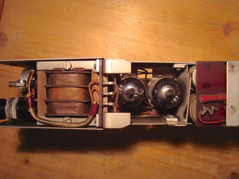
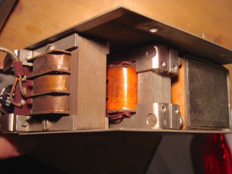
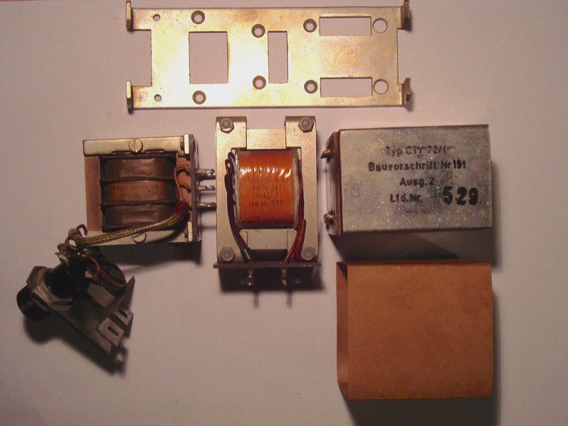
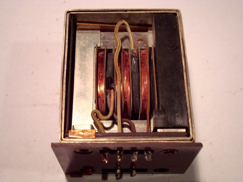
Output Transformer & Plate Choke
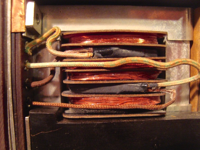
The choke (inductor at the second tube's anode) is wound in three sections to minimize stray capacitance. The output transformer has several cylindrical primary and secondary layers going on top of each other; the leads going to the individual sections can be seen at it's sides. Although sitting in close proximity to the inductor, the different orientation of the windings prevents unwanted coupling, so they don't need any shielding.
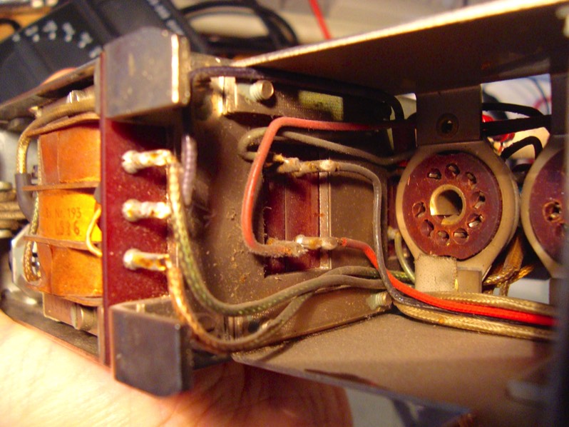
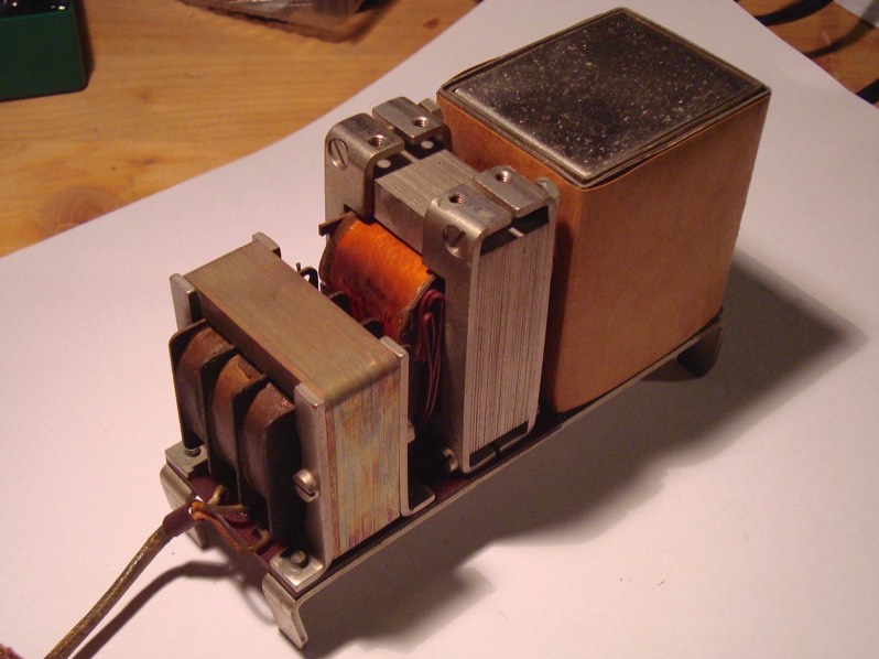
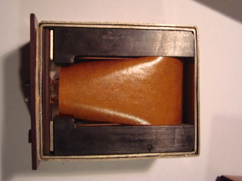
Input Transformer
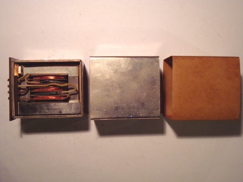
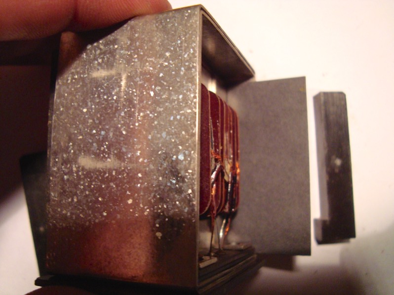
The input transformer is one marvellous example of engineering and precision crafting from the old days - check out those pictures. The screening can consists of two square shells that perfectly fit together, but can be pulled apart easily. Actually, each is made up of two layers of MuMetal with a layer of copper foil inbetween.
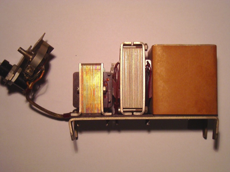
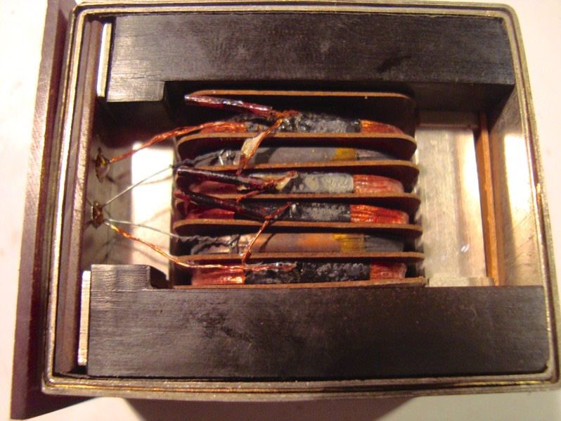
The inner surfaces of the screening can are isolated from the transformer laminations by layers of cardboard (top and sides) or a layer of bakelite (at the base), respectively. Only one of the four mounting screws makes electrical contact with the screening enclosure and the laminations, the other three go through insulation tubing into bushings inside those dark grey "sticks", which are of none-conductive material and also act to hold the transformer in place without it touching the screening can.
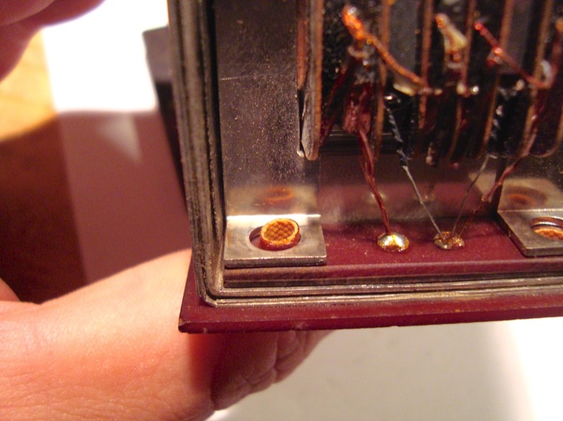
With the screening can being wrapped in a layer of paper also at the outside, and it's base resting on an additional layer of bakelite, electrical contact to any other external metal surface is made at one point only - namely by one of the four screws -, giving the designer maximum flexibility regarding fine details of the grounding scheme, which obviosuly does make a difference in certain situations. As mentioned in the "Service" section, this arrangement e.g. facilitates the different grounding scheme of the V77 (high gain version of V72).
The actual winding scheme is designed to have several separate sections ("discs") in order to maximize coupling and minimize stray capacitance: Two primaries, each one sandwiched by two secondaries, plus faraday shielding of the primaries by wrapping them in conductive foil. The primary windings are fed to separate input pins, so as to either have them in series including the high pass arrangement in the V72, or to have them in parallel and get 6dB more gain (as done in the V78, yet another sibling of the lot). As for secondaries, all four discs are connected in series internally, with the "hot" end fed to one pin and the "cold" end, together with the leads from the faraday shield, fed to the other.
A copy of the original blueprints (in German) is here.
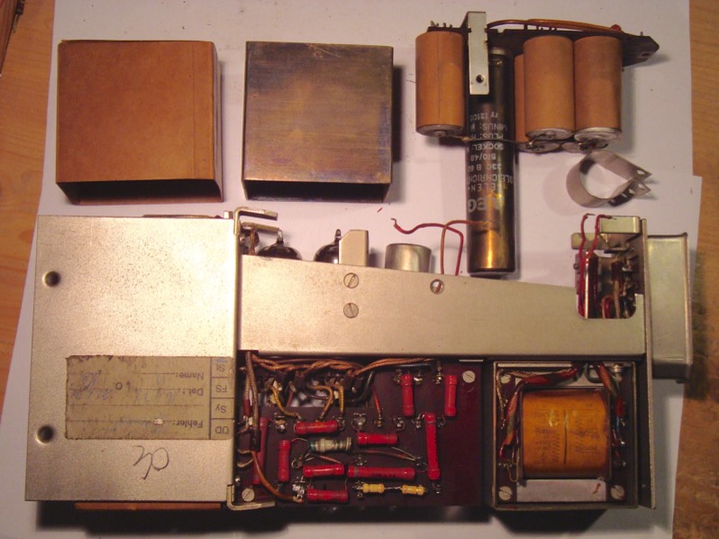
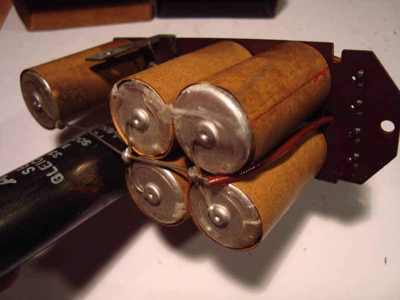
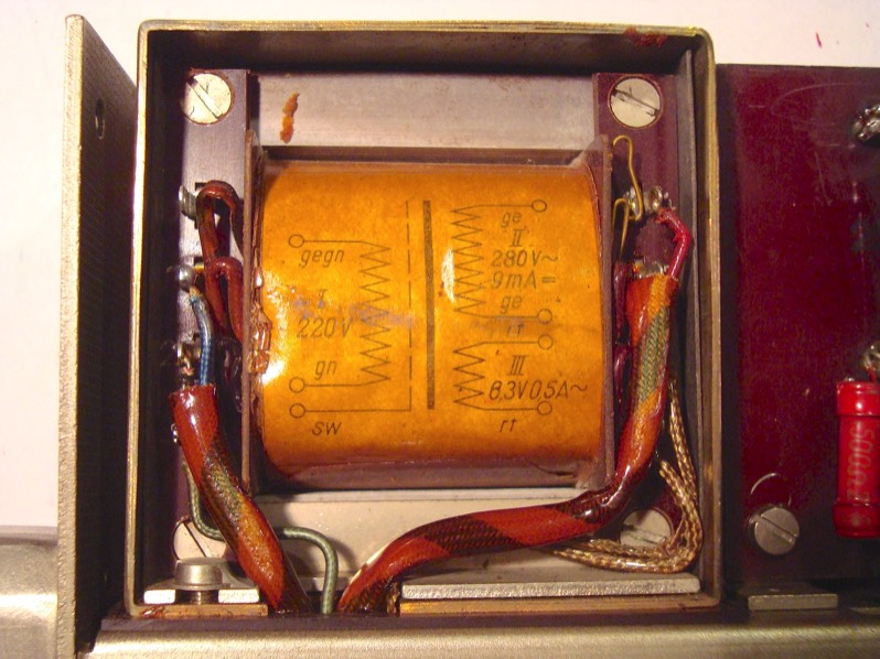
PSU Section
While I'm at it, and to more or less complete the dissection, I'm removing the mu metal cover of the mains transformer to have a peek inside. Having the PSU section taken off, I should actually replace those 50+ year-old filter capacitors right away - however, since I don't have the right values handy, I'll have to do that another time. In any case, the enormous size of that bridge rectifier (the long black cylinder) never ceases to amaze me!