V72 - Description
The V72 is the blueprint of a modular amplifier range designed for several applications such as radio/TV broadcast, recording, vinyl cutting etc. It was built during the 1950's and 1960's mostly by Siemens, but also Telefunken and Maihak. A V72 weighs several kg, doesn't have any controls and does nothing but apply a fixed gain of 34dB to the signal - but that, it does beautifully. It is meticulosly engineered with high attention to detail of both circuitry and construction, however, the fact that the physical layout is rather stuffed due to restrictions of module size can make it a pain to work on. Plus, the 50+ years old wires are prone to break with relatively small strains, and their insulation is likely to crumble away. To access some of the components, you have to unscrew and desolder whole blocks of the circuit... like I had to when servicing the unit in question.
The V72 is the blueprint of a modular amplifier range designed for several applications such as radio/TV broadcast, recording, vinyl cutting etc. It was built during the 1950's and 1960's mostly by Siemens, but also Telefunken and Maihak. A V72 weighs several kg, doesn't have any controls and does nothing but apply a fixed gain of 34dB to the signal - but that, it does beautifully. It is meticulosly engineered with high attention to detail of both circuitry and construction, however, the fact that the physical layout is rather stuffed due to restrictions of module size can make it a pain to work on. Plus, the 50+ years old wires are prone to break with relatively small strains, and their insulation is likely to crumble away. To access some of the components, you have to unscrew and desolder whole blocks of the circuit... like I had to when servicing the unit in question.
Physical Layout
The amp was built to the highest standards at the time of it's design, with heavy duty steel chassis, specially designed transformers, a circuit board for the smaller components (as opposed to point-to point wiring mostly used then) in order to fit everything into the challenging dimensions of the module, as well as EF804s tubes for longevity and low noise.
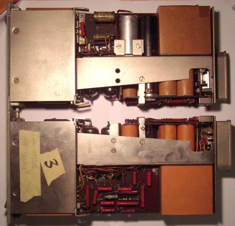
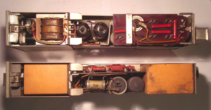
With a high impedance circuit like this and size restrictions which limit the options for optimum layout, several measures were taken to achieve the lowest possible noise floor; the mains transformer sits in a mu metal enclosure located on the right, well away from the rest of the signal transformers and inductors behind the sheet metal on the left. The input transformer has heavy duty shielding by two layers of mu metal with copper foil inbetween. Input and mains transformer only make direct contact with the chassis by one screw each. To avoid multiple ground return paths, any other contact is prevented by bakelite bases and paper sleeves around the rest of their surfaces; the same goes for the PSU filter capacitors.
The top of the larger circuitboard (picture above) hosts most of the resistors plus two small capacitors for the feedback loop, with the rest of the non-electrolytic caps on the backside (screen and interstage cap to the left, the big output cap more to the right… plus the (relatively large) black cylindrical rectifier. The picture below shows top and bottom view, with the PSU filter resistors and mains transformer to the right, and input transformer, plate choke and balancing pot for the heater supply to the left. If you look hard, you will even find the component numbers printed on the circuit boards - most of them have faded over time, though.
Circuit Description
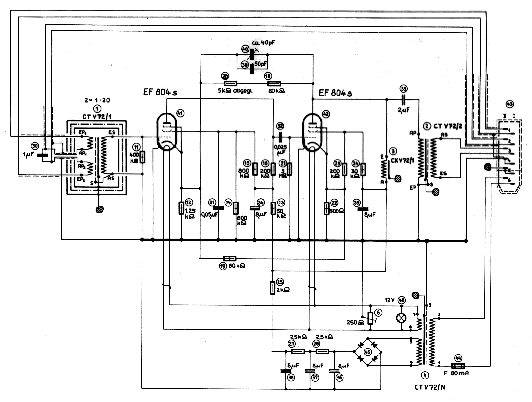
As for the actual circuitry (see below), we have two pentode stages in a common cathode configuration, with DC coupled voltage feedback from anode #2 via R18 & R20 back to cathode #1 (R12). To allow for a larger output voltage swing at minimum distortion, there is an inductor as the plate load of the second tube. In addition to individual current feedback at the cathode resistors, cathode #2 is connected to cathode #1 by R19, providing another feedback path which further decreases output impedance.
As to comply with a bandwidth limitiation of 40Hz to 15KHz required for broadcast application, the V72 has both highpass and lowpass filters incorporated: Capacitors C39 / C40 within the voltage feedback loop are responsible for the high frequency rolloff (C40 is depicted as adjustable, but actually has a fixed, factory selected value). The actual value of R18 is chosen to set the gain exactly to 34dB. Low frequency roll-off is accomplished by virtue of capacitor C30 which sits inbetween the input transformer's primary windings and gradually increases it's impedance for frequencies below 40Hz. This also reduces distortion by preventing the transformer (which actually is the limiting factor regarding the max. broadband output of +16dBu) from being overloaded by excess low frequencies. If desired, the filter can be bypassed by connecting pins 2 (I&II) at the rear connector.
To match the high impedance tube circuit to the outside world, the input transformer is wired for a 1:10 ratio, which lowers the input impedance of the first tube stage to 2KΩ and also gives 20dB voltage gain, improving signal-to-noise ratio. The two pentode stages provide another 35dB of gain, yielding 55dB in total. The 11:1 output transformer does step down the overall gain to the specified 34dB but also acts to reduce the plate load of the second stage to a required low value of around 50Ω.
The PSU section is made up of the regular bridge rectifier and RC ripple filter arrangement for the anode supply. In order to minimize hum pickup from the AC filament supply within this high impedance circuit, the filament voltage is made symmetrical to ground by virtue of a potentiometer (R6) which can be adjusted at the front of the module. Note the grounding scheme of the transformers and plate inductor - iron cores and casings are attached to chassis, faraday shields are at 0V potential.