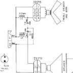
crossover schematic
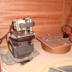
location in cabinet
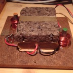
cover removed
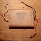
original double capacitor
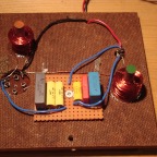
refurbished crossover
LESLIE 147
Crossover Service
The crossover divides the signal coming from the amp into to bands of frequencies and feeds them to the horn driver and woofer. It consists of two capacitors and two inductors, each LC pair forming a filter with slope 12 dB/Octave. The parts are situated inside a cylindric enclosure behind the lower motor stack.
Opening it up reveals the two inductors and actually just one more box with three leads, in which the two single capacitors are incorporated (the piece of cork is just there to hold that box, which is merely glued to the cardboard, in place against the cabinet).
Measuring their values gave 14uF and 30uF, where there actually should be 7.2uF and 12.5uF respectively. In contrast to electrolytic capacitors, which tend to dry out over time and loose capacitance, these capacitors here are made of metalized paper, which, over many years, absorbs quite a bit of moisture and thus increases capacitance considerably.
The doubling of capacitances meant that the crossover frequency had dropped by an octave, from 800Hz to 400Hz. Thus, the horn driver received a lot of low mids; these are normally sent to the woofer, but now made the horn driver crap out, since it wasn't designed to handle high levels at that low a frequency range. In addition, the doubling of capacitance affected the high frequency rolloff inherent to the circuit, also reducing it by an octave.
To replace the original part, I got some metalized film capacitors (MKP or FKP), rated for 63 or 100 volts. Since the specific values I needed aren't available anyway (except for custom parts like this here, which also has a custom price tag, though), I got several units and values to combine.
In a crossover, you really want the values to be exact, so I measured the actual capacitances of all units I had (which may well be off from the printed value due to tolerances), put those needed for each original capacitance in parallel (as you can see on the picture, that's three caps each), soldered them to a piece of circuit board and screwed that to the original cardboard holder of the dividing network.
Bottom line: If your Leslie sounds off and the crossover is still original, that's the first suspect
With the refurbished crossover, the sound was much more balanced, and instead of gross distortion, there was some pleasing saturation increasing gradually with level. I was still missing some low end, when I realized that I hadn't put the cabinet's middle back panel in place! For low frequencies, this results in acoustic cancellation between front and back of the woofer... 'doh ;-)
However, ...
With the middle panel back on, the low end finally seemed in the ballpark of a classic 147... but the highs didn't. Engaging the higher drawbars resulted in an overly bright sound - with the mids somewhat scooped out, even - and the key click was more noticeable than usual.
The suspect for that would probably have to be the non-original horn driver - but since I was going to check the amplifier anyway, to see if any parts were aged and needed replacing, I went into that first. This way I could also rule out any possible defects in frequency response coming from the amp.